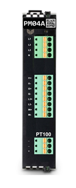
PM04A
The PM04 is a new generation of Power Measurement module measures electrical energy in a three-phase supply network. The voltage is measured via direct connection to the three phases and neutral. The current of the three phases and neutral is measured via current transformers (1A or 5A), or via Rogowski coils. The module calculates active/ reactive/ apparent power, power factor, phase angle and frequency using two micro-processors on the module (one for processing data and one for transmitting data via the backplane bus to the main CPU).
Comprehensive data/metrics up to the 63rd harmonic permit extensive network analysis to optimize the supply to a drive or machine. Insulation failures can be detected via current measurement performed in the neutral conductor to protect equipment from damage and failure.
Additionally, the module can connect to the PT100 sensor to measure temperature with 16-bit resolution for assessing transformer, ambient, or other component temperature.
Power Measurement
3 voltage measurement inputs, 4 differential current
measurement inputs.
Input resistance voltage path: 1429 KΩ
Measurement Resolution [bit]: 24 Bit
Input resistance current path type: 200 mΩ
Frequency range: 0..3300 Hz
Frequency range power supply: 45..65 Hz
Max measurement current (RMS): 1A
Max measurement rated voltage: VLN=400VAC, VLL=690VAC
Temperature Measurement
1 PT100 measurement inputs.
Resolution: 16 bit
Update time: 4 ms
Input resistance current path typ.: 22 mΩ
Accuracy (at 25°C): ±0.1%
Temperature drift: ± 25ppm/°C ± 25ppm/°C
Power-freq. noise rejection: 50Hz
Introduction to LB2 I/O Series
The Brodersen LB2 I/O modules are designed for the RTU32M & RTU32N series. The I/O modules are in two parts, a bottom part containing the backplane bus, and a top part containing the I/O board and logic. All LB2 modules are hot swappable and equipped with a 200 MHz processor to process I/O, handle filtering, SOE, debounce, module clock and general module logic. Diagnostic variables are available for all LB2 I/O modules. Please see the module datasheets for full info.
Module firmware update is handled at the RTU level from the Brodersen WorkSuite.
Use only genuine Brodersen bus cables for connection to Brodersen RTUs and for extension of I/O module blocks. The connection cables for the LB2 backplane bus are designed to meet the power requirements and shielding to run high speed communications. The maximum overall length of a complete system is 40 meters. Each LB2 I/O module & power supply module is calculated as 2 cm. The cables are as the length indicates, e.g. UCC-610/1 count as 100 cm.
The maximum system configuration is 60 I/O modules on one LB2 Bus. If the configuration exceeds 60 I/O modules, an additional CPU is required.